Get in touch with Tengyang Company

Measurement at a glance
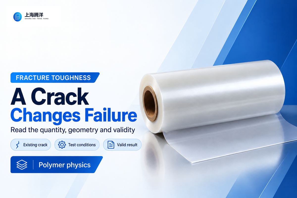
Object: a specimen containing a sharp crack. Common outputs: K in MPa√m; G and J in J/m². First decision: identify the material, crack path and deformation before choosing a test.
Fracture toughness is a material’s resistance to extension of an existing crack under specified conditions. Tensile strength alone can’t answer this question. A small edge defect changes the local stress field. Therefore, a strong-looking sheet may fail differently from an otherwise similar unnotched specimen.
Fracture toughness describes resistance to crack extension. K values use stress multiplied by the square root of length; energy-based values use energy per area. Match the reported quantity and test conditions before comparing materials.
Key points
- A material with greater single-load toughness can still have poorer fatigue resistance in a particular comparison.
- A conditional KQ result becomes KIc only after the applicable validity checks.
- Thin ductile films have a dedicated essential-work method, with stable-growth requirements.
- Laboratory capability, certification and the price of a complete test are separate questions.
What fracture toughness measures
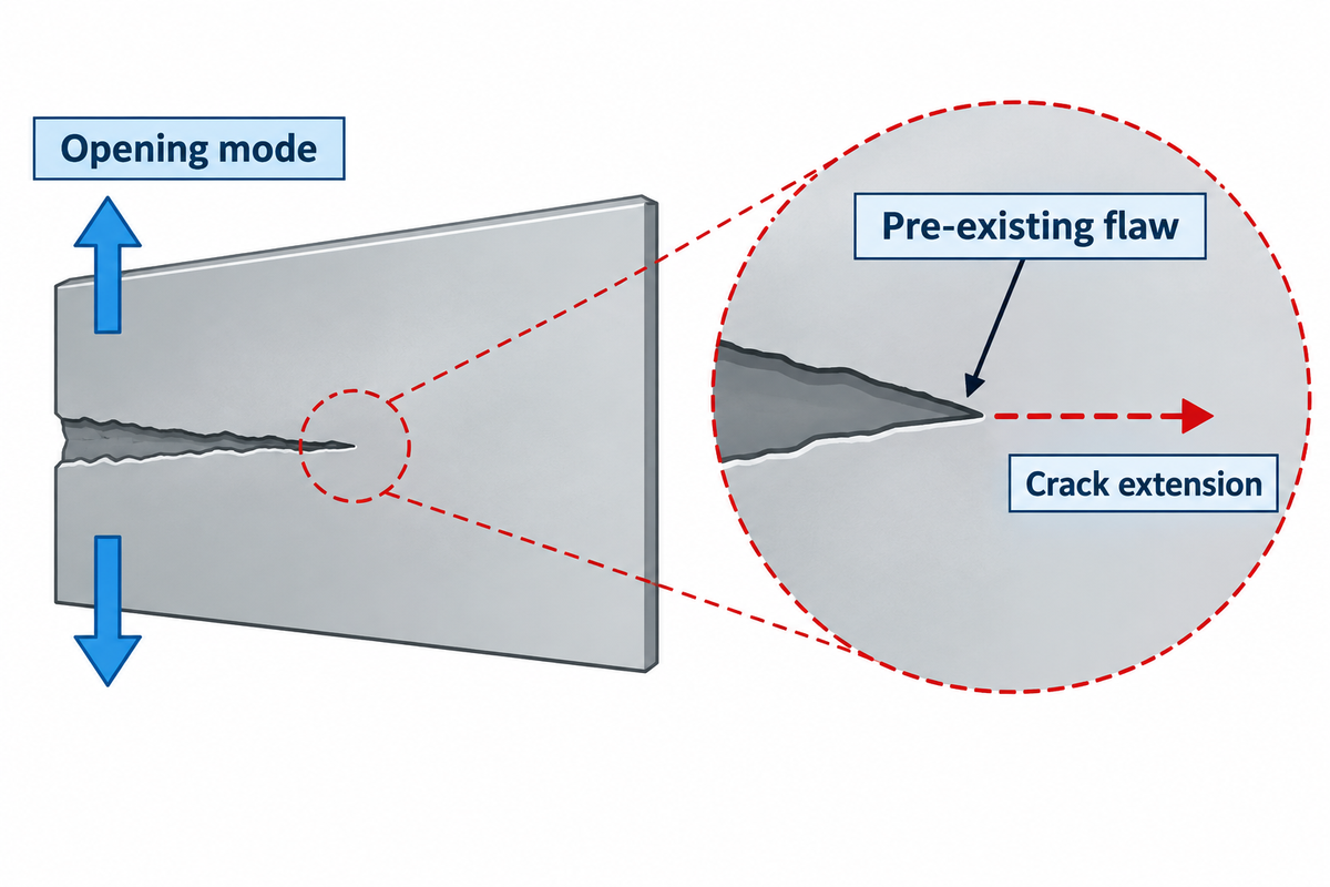
Fracture toughness measures resistance to crack propagation or initiation, depending on the reported parameter and test; the test asks what driving force is needed to propagate a pre-existing flaw. Fracture mechanics treats the existing flaw as part of the problem. The dimensions and loading of the flaw determine the driving force, and the material response determines whether the crack extends.
In opening mode, Mode I, the faces of the crack separate from one another. In Mode II, there’s in-plane sliding, and Mode III involves out-of-plane tearing. A mixed-mode result may consist of different loading, and therefore an opening-mode value can’t describe all possibilities of crack extension. The University of Cambridge’s brittle-fracture teaching package describes crack-driving force and material resistance, and how they relate to stable and unstable extension.
Suppose there’s a film screening project. An engineer receives two tensile reports, both from smooth strips, but the part under consideration has a cut edge next to a fixing point. The reports show how the strips carried the load; neither includes the edge defect in the test geometry. The next logical step would be to find the edge defect and identify its loading direction, and choose an appropriate pre-cracked test. Microscopic damage or microcracks may matter during failure, but their presence does not yield a measured toughness value. The comparison will connect the failure mechanism observed in the part to a test that captures the crack process relevant to that failure.
Further information about molecular structure and mechanical behavior of polymers and related areas can be found in our polymer physics resources.
Strength, toughness and fracture toughness
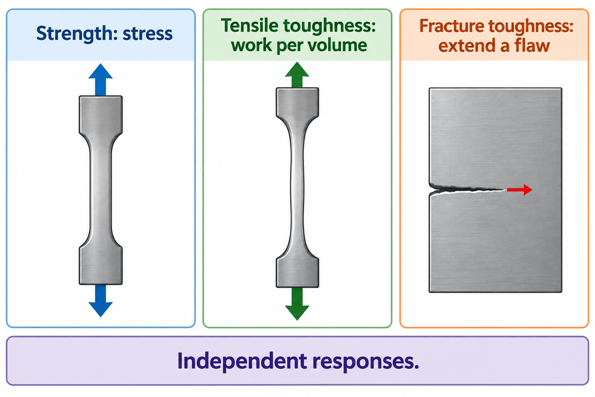
In materials science, strength is defined as a stress at yielding or failure. The term ‘tensile toughness’ refers to the work absorbed per original volume as a specimen stretches to failure. The term ‘Crack resistance’ addresses a different question: how much driving force is needed to extend a flaw already present? These mechanical properties can change independently.
During tensile testing, elongation and the area under the stress-strain curve aid in describing deformation and absorbed work. Ductility is concerned with the level of deformation before failure. None of these measurements by itself provides a sharp-crack threshold. A steel alloy selected for high yield strength still needs to be assessed for crack resistance if a flaw is relevant to engineering design.
Impact tests also study how specimens resist fracture under their own loading conditions. The Charpy impact test records specimen behavior under its prescribed impact, specimen and notch conditions. Results of Charpy and Izod tests depend upon the test configurations. A v-notched impact bar isn’t equivalent to a fracture specimen containing a sharp pre-crack because of the notch root radius. This changes the local conditions.
TWI’s EDF assessment touches upon correlations in certain ferritic steels and explains why limitations on material, energy and temperature prevented some correlations from answering the assessment question. Such correlations need their own validation; for a polymer without a validated correlation, measure crack resistance with an appropriate pre-cracked test instead of converting impact data.
Fracture toughness units: K, G and J
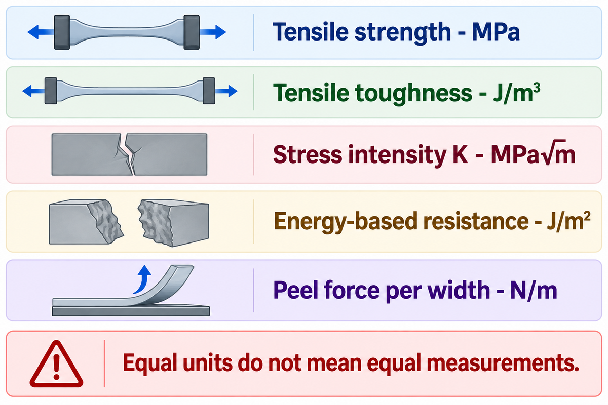
The unit tells you which quantity was measured. Stress intensity K, in general, is given in MPa√m. Energy release rate G and J-integral make use of energy per area and are in J/m² or kJ/m². Work done by a tensile load per original volume is given in J/m³. In peel testing, the result is often expressed in N/m or force per width of the peel specimen.
5-Quantity Toughness Map
This map is used when a laboratory report and a material datasheet seem to describe the same property. The last column shows what’s missing to arrive at a conclusion.
| Quantity | Typical unit | What it describes | Comparison requirement |
|---|---|---|---|
| Tensile strength | MPa | Stress at a specified tensile limit | Use the relevant strength definition and test conditions |
| Tensile toughness | J/m³ | Work absorbed per original volume | Keep the stress-strain basis and specimen conditions consistent |
| Critical stress intensity | MPa√m | Crack-tip field at a specified fracture condition | Check mode, geometry and linear-elastic validity |
| Energy-based crack resistance | J/m² | Energy-related resistance to creating crack area | Identify G, J, initiation or growth resistance |
| Peel force per width | N/m or N/mm | Measured force normalized by strip width | Identify geometry, deformation and failure path |
Dimensionally, 1 J/m² equals 1 N/m. That identity doesn’t make a peel result an intrinsic fracture energy. The peel-strength interpretation guide explains why geometry and the tested assembly belong with the reported number.
What is the difference between stress intensity factor and fracture toughness?
The stress intensity factor specifies the crack-tip loading field for a given load and geometry. A critical stress intensity factor specifies the value for a particular fracture condition. Comparing those two parameters is meaningful only if their loading mode, material state, and the underlying fracture model are compatible.
Other fracture parameters describe different aspects of deformation. CTOD means crack tip opening displacement and has a unit of length. An elastic conversion between K and G requires appropriate modulus and stress-state assumptions. Atkins, Lee and Caddell’s 1975 PMMA study discusses the issue of selecting an appropriate modulus, given that the polymer response depends on the testing rate.
How crack size changes the failure stress
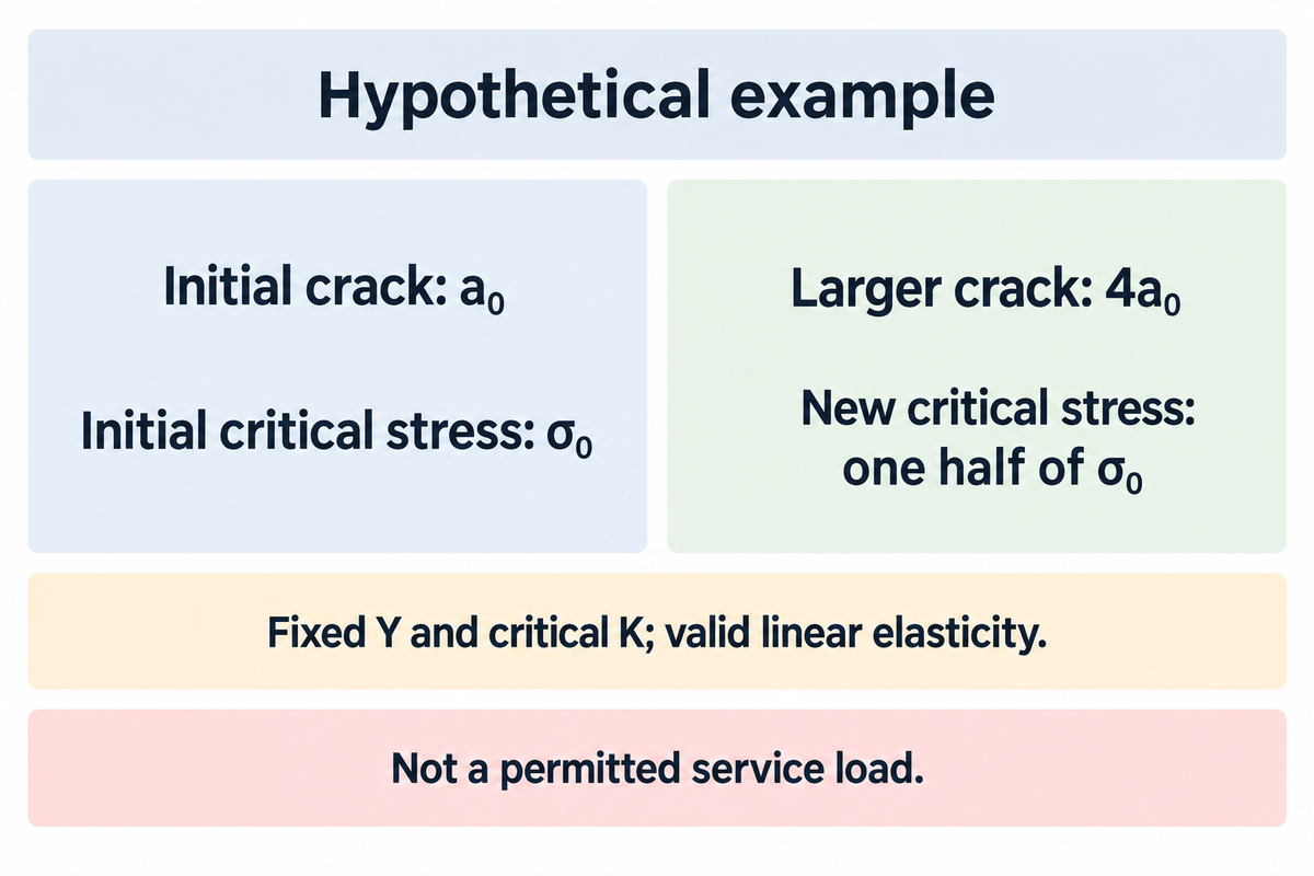
Under a linear-elastic opening-mode model, increasing crack length raises the stress intensity even though the nominal applied stress doesn’t change. The geometry correction must also be known. These fracture mechanics concepts describe why a change in the size of a flaw can result in a change of the failure condition without a change in the material.
How is fracture toughness calculated?
A standardized test derives a candidate fracture parameter from measured loads, specimen dimensions, and prescribed geometry relationships. A simple linear-elastic example shows K = Yσ√(πa), where σ is the nominal stress, a is the defined crack dimension, and Y is a geometry factor. A candidate fracture parameter determined by the equation still requires the method’s validity checks.
NDE Education has a fracture-toughness explanation, which provides a similar relationship using β to represent the geometry factor. In this case, Y is used to represent that factor. The definition of a depends on the specimen: it can be an edge-crack length or half the length of an internal crack. Using the wrong definition changes the value obtained.
For this hypothetical example, it is assumed that the geometry factor is fixed and so is the critical value of K. Linear elasticity is assumed to remain valid. Let the initial crack dimension be a0 and the critical stress be σ0. For a new crack dimension of 4a₀, the stress ratio is √(a₀/4a₀) = 0.5. At twice the starting dimension, the ratio is 1/√2, approximately 0.707. This compares sensitivity to flaw size; it does not establish a permitted service load, because real geometry, residual stress and plasticity can change the assessment.
| Crack dimension / a₀ | Calculation of stress ratio | Critical stress / σ₀ |
|---|---|---|
| 1 | √(1/1) | 1.000 |
| 2 | √(1/2) | 0.707 |
| 4 | √(1/4) | 0.500 |
Calculating a critical crack size for an actual part requires the actual geometry, as well as a suitable fracture toughness of the material. A spreadsheet containing only loads and crack lengths wouldn’t be able to supply all the missing assumptions.
When KQ qualifies as plane-strain fracture toughness
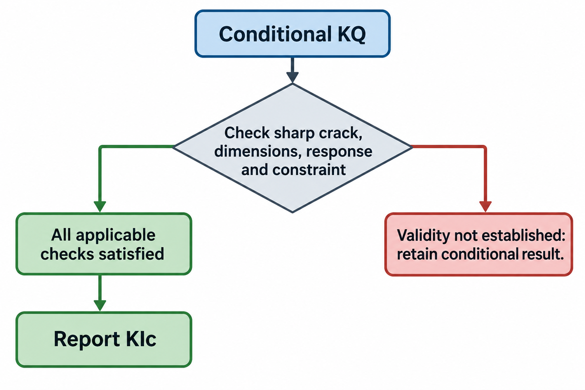
KQ is a conditional result that must satisfy all applicable test-procedure requirements to be reported as plane-strain fracture toughness, KIc. Crack sharpness, specimen dimensions, loading response and crack-tip constraint are considerations. It can’t be assumed that all these conditions are met with a mere numerical output from the test machine.
What is plane strain fracture toughness?
Plane strain fracture toughness defines the opening-mode crack-resistance value obtained under sufficiently restricted, predominantly linear-elastic conditions. Constraint limits deformation through the specimen thickness. The size of the plastic zone must be compatible with the method’s assumptions and the specimen must fulfill the validity criteria for the result to be reported as KIc.
“Specimen thickness must be sufficient to ensure this stress state.”
ASTM D5045 addresses plastics. ASTM E399-24 addresses metallic materials. Criteria drawn from the metal method should not be copied into a plastics report without checking the applicable procedure. Thick plates and thin sheets can develop different constraint; thickness alone is not a universal pass/fail number.
A plastic zone at the crack has the potential to absorb energy through plastic deformation. If this zone at the crack tip becomes too large for the assumed model, a different characterization route may be necessary. Tip blunting alters the local geometry. A better question to ask for a test report is “has the validity of the test been documented” rather than “is the reported KIC high”?
Choosing a fracture toughness test for plastics and films
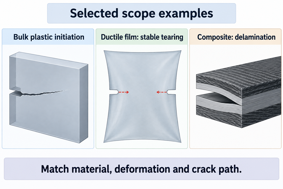
A test should be selected based on the material form under consideration, the deformation behavior and the crack path. Bulk plastic initiation, stable tearing of a ductile film and delamination of a composite, for instance, are different measurement problems. A method-selection table is more valuable than a prescribed test, as each different route addresses a different crack-resistance question.
| Material or crack-process category | Method or route | Reported purpose | Decisive boundary |
|---|---|---|---|
| Bulk plastics with suitable linear response | ASTM D5045-14(2022), CT or SENB | Initiation KIc and GIc | Sharp crack and valid constraint/linearity |
| Metallic material | ASTM E399-24 | Plane-strain KIc | Metal-specific validity requirements |
| Plastics with slow stable extension | ASTM D6068-10(2026) | J-R resistance curve | Suitable stable growth and measurable crack front |
| Ductile polymer films and thin sheets | ISO 23524:2022, DENT | Essential work of fracture | At most 1 mm thick; stable growth under plane stress |
| Unidirectional polymer-matrix composite | ASTM D5528/D5528M-21, DCB | Mode I interlaminar GIc | Delamination in the specified composite system |
| Ultrathin experimental film | Study-specific supported or free-standing method | Defined fracture-energy response | Support, geometry and material must accompany the result |
| In-plane sliding crack, Mode II | Material-appropriate sliding-mode procedure | Resistance under in-plane shear | An opening-mode value does not characterize this loading mode |
| Out-of-plane tearing crack, Mode III | Material-appropriate tearing-mode procedure | Resistance under out-of-plane shear | Identify the tearing geometry and mode-specific analysis |
| Combined opening and shear | Mixed-mode procedure for the material and crack path | Resistance at a defined mode combination | Report the loading mixture rather than treating it as pure Mode I |
CT means compact tension. SENB is a single-edge-notched bend test, commonly arranged in three-point bending. As the specimen is loaded, relevant force and displacement records support the method’s analysis. Fatigue pre-cracking can create a sharp crack in appropriate procedures, but its suitability and implementation must adhere to the material standard.
ASTM D6068 provides a resistance-curve route for plastics that undergo slow stable crack growth. ISO 23524 covers the essential work of fracture, or EWF, in ductile films and sheets using double-edge-notched tensile specimens. Fast brittle growth driven by stored elastic energy makes that sample unsuitable for the EWF method.
ASTM D5528/D5528M addresses a different path: interlaminar separation in specified unidirectional composites. The double-cantilever-beam geometry does not turn a laminate result into a bulk polymer KIc.
For a hypothetical flexible laminate, first determine where failure is occurring. A failure through the film gives one type of evidence, and failure by adhesive separation gives different evidence. If the project is regarding a TPU film, then the material name alone won’t define the test. A ductile free film is a candidate for the EWF route when it is at most 1 mm thick and shows stable crack growth under plane stress. A bonded assembly requires consideration of the adherends and the failure path. If the main concern is peel performance, then use the existing guide to define flexible laminate peel specimens, to frame that separate measurement.
Why fracture toughness values change with test conditions
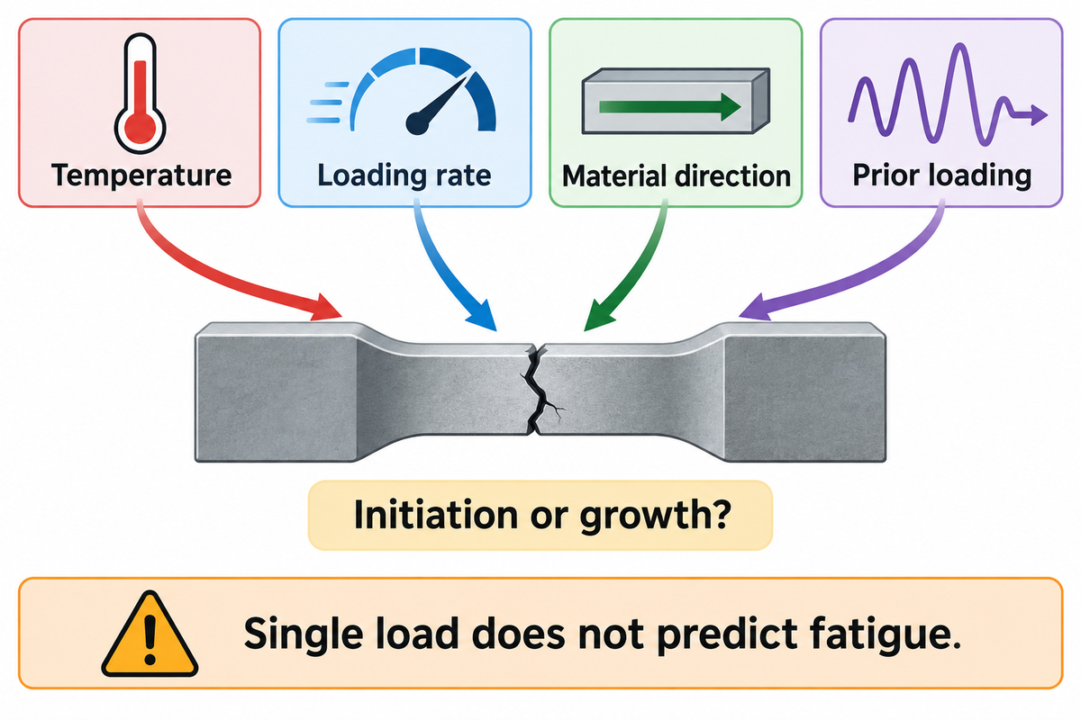
Fracture toughness values depend on the state of the material and the conditions under which failure is measured. Temperature, rate, orientation and prior loading can affect deformation near a flaw. Results measured at different strain rates need special attention. Compare those conditions before ranking results, especially if one report describes initiation and the other follows the material as the crack grows.
Atkins, Lee and Caddell’s PMMA experiments demonstrate a universal temperature rule’s unreliability. The historical results show changes in the direction of the toughness response as temperature and speed varied simultaneously across different conditions for Plexiglas G, not all polymers. The site’s viscoelasticity explanation gives a broader account for time-dependent behavior.
Hunston and colleagues’ 2000 NIST research record provides another variable, “high-load hold history.” Among the rubber-toughened epoxies studied, longer “holds” increased the measured toughening. At very slow test rates, significant permanent deformation and resistance-curve behavior violated the linear-elastic approximation.
Single-load toughness can’t predict cyclic behavior. Among double-network elastomers studied in 2021, the formulation exhibiting lower monotonic toughness showed higher fatigue resistance. This is a bounded experimental counterexample not a ranking of TPU grades. Repeated-loading questions pertain to fatigue testing and the fatigue crack growth measurements.
Compare
- Match temperature and strain rates.
- Identify initiation or growth resistance.
- Record material direction and conditioning.
Avoid
- Rank unmatched fracture parameters.
- Treat single-load results as fatigue life.
- Hide invalid tests inside an average.
How much does polymer fracture testing cost?
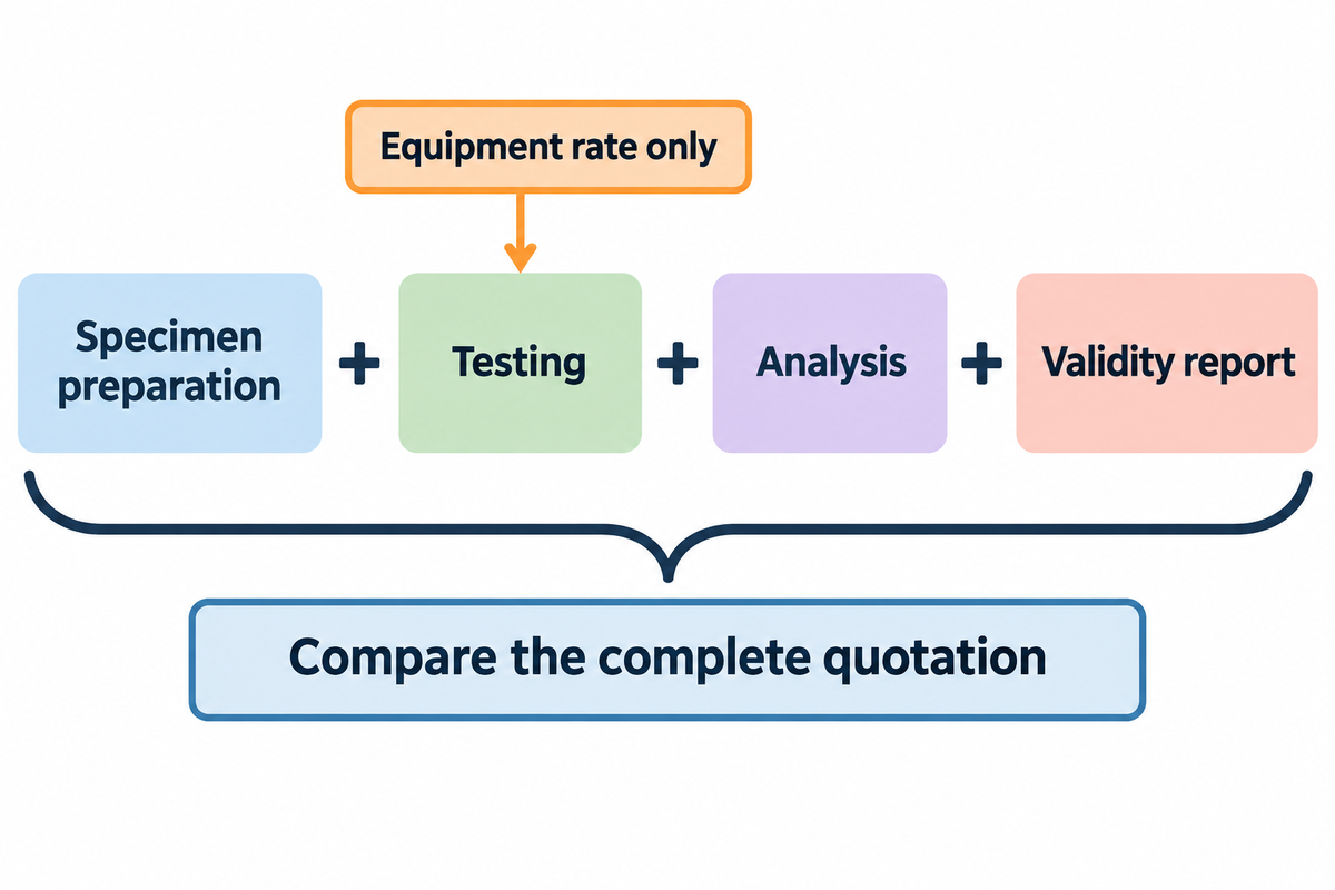
Public examples of equipment rates are $75 per hour for external electromechanical load frames at the Colorado School of Mines. A complete polymer fracture test would warrant a quote for specimen preparation, testing and analysis. Compare the same procedure, conditions and reporting scope before treating a lower total as better value.
Colorado School of Mines’ fee schedule, effective May 1, 2026, lists the external electromechanical load-frame fee at $75 per hour. This is an equipment rate and not a D5045 package rate. The fee schedule doesn’t establish the hours, specimen preparation or analysis required for your sample set.
Assume a hypothetical comparison contains two material grades, two conditions, and five specimens per combination. The requested scope contains 2 × 2 × 5 = 20 specimens; five is an assumed planning count, not a replicate requirement taken from a standard. One quote may include machining and crack preparation, while the other may start with finished specimens. The totals won’t be comparable until the tasks are aligned. Inquire as to how an invalid test is reported and charged, and whether another specimen is needed to obtain the intended result. A good purchasing decision is made from aligning the work, rather than splitting two dissimilar totals by the same sample count.
This comparison lines up the method boundaries within a quotation request. It’s a purchasing aid, not a substitute for the selected test procedure.
| Comparison field | Information to align | Why it changes the comparison |
|---|---|---|
| Material identity | Grade, processing history and orientation | A different material state may change the measured resistance |
| Form and thickness | Bulk specimen, ductile film or bonded assembly | The EWF scope applies to suitable films and sheets, not every form |
| Crack path | Through the material or between layers | Interlaminar testing answers a different question from bulk fracture |
| Loading mode | Opening, sliding, tearing or a defined combination | Pure opening and mixed-mode results are not interchangeable |
| Output parameter | Conditional K, valid KIc, initiation G or a resistance curve | A single initiation value does not describe an entire growth curve |
| Specimen preparation | Who machines the shape and prepares the sharp crack | D5045 requires the appropriate crack and specimen conditions |
| Test conditions | Temperature, loading rate and conditioning | Unmatched conditions can change the apparent material ranking |
| Validity and repeat work | Validity reporting and treatment of unsuccessful specimens | A machine output and a valid transferable result are different deliverables |
| Commercial scope | Preparation, machine time, analysis and report | An equipment-only hourly rate cannot establish the complete test price |
- Define the failure question. State the material form, crack path and intended comparison.
- Agree the method and sample scope. Confirm preparation, conditions and required specimen count with the laboratory.
- Compare the complete quotation. Include data analysis, validity reporting and the treatment of unsuccessful tests.
Finding an ASTM D5045 testing laboratory
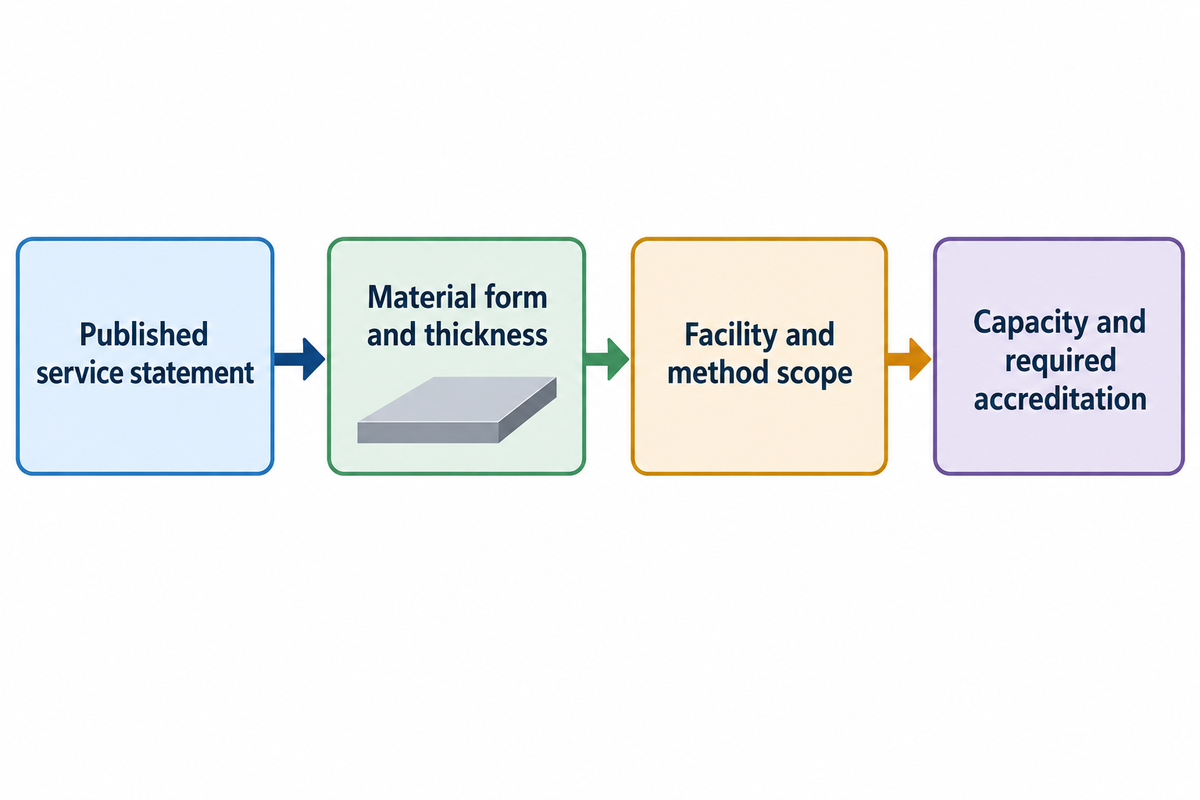
Start with a laboratory page that explicitly names ASTM D5045 for polymers, and then match the service to your specimen and the report that is required. A general-purpose fracture-testing machine is not sufficient evidence of a particular test method. If certification or accreditation is required by your project, obtain the relevant facility and method scope.
Ghent University’s Mechanics of Materials and Structures group lists thermoset and thermoplastic polymers among its materials and CT and SENB fracture testing among its services, with D5045 among the listed standards. The University of Southern Denmark’s FFM laboratory also has polymer D5045 testing on their site; their page states that the laboratory isn’t certified and has a 2019 editorial date.
These are published service statements, not a prioritized laboratory shortlist. Provide the proposed material form and thickness with your request. For each case, ask for the applicable edition, the responsibilities for preparation, the form of the results and the consequences of validity failure. Ask the laboratory to indicate available capacity and any necessary accreditation in its response to your request for quotation.
Industry Outlook
Recent thin-film research is improving how small specimens can be measured, while established standards define separate routes for different fracture behavior. The most relevant improvement to a materials team is more detail about the measured film and crack process. It doesn’t mean there will be a universal toughness number for all polymer forms.
In their 2025 DPP polymer-film study, Zhang and colleagues studied pseudo-free-standing films using a pure-shear method. Thin-film fracture energies were strongly dependent on film thickness and molecular structure. The authors studied the effects of post-processing thermal treatments. Those annealing temperatures describe the history of the process, rather than the service conditions to be used for a generic material.
Earlier, in Zhang and colleagues’ 2021 polystyrene study, water-supported thin films were used. An 80 nm film with a molecular weight of 173 kg/mol yielded a fracture energy of 995 J/m² using that method. The authors mentioned the role of the supporting water and the need to study completely free-standing films. This particular example illustrates why a very thin film’s support and analysis method must remain attached to its result.
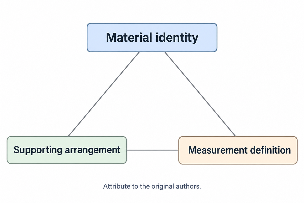
The practical direction is to maintain more of the experimental context when assessing new materials. A reported value for a supported research film should carry its supporting arrangement, material identity and measurement definition. The definition of a measurement should be clear. A photo of the fracture surface can assist in identifying the location of failure, but it can’t substitute a quantitative analysis. Distinguishing manufacturing changes that alter the material’s structure and changes to the test itself is essential.
On the standards side, ASTM lists D6068-10(2026) as active. This designation, in itself, doesn’t indicate new technical requirements. The EWF route in ISO 23524:2022 already provides a separate framework for suitable ductile films. When assessing new materials, teams can start from these frameworks, and then determine where research-specific processes provide answers to questions that the standard specimen cannot. Observations should be attributed to the original authors, and should not be stated as measured performances by a film supplier.
Frequently Asked Questions
Is fracture toughness a material property?
Material and test conditions
Yes, a valid fracture-toughness result characterizes a material under stated conditions, but the property is not a context-free constant. Material grade, orientation, temperature, loading rate and test method matter. A conditional result from an invalid specimen should not be treated as a transferable plane-strain value. Compare reports that identify both the measured quantity and its conditions.
Can KIc be obtained from the Charpy test?
Direct measurement and correlations
A Charpy test does not directly measure KIc. It records impact behavior using its own specimen, notch and loading conditions. A valid KIc test instead evaluates a sharp crack under the applicable fracture-mechanics procedure. Empirical correlations can exist for particular materials and conditions, but those correlations need independent validation for their intended use.
Does high fracture toughness mean high strength?
Different material responses
No. Strength describes the stress associated with yielding or failure in a specified test, while fracture toughness addresses resistance to extension of an existing crack. A processing change can affect these properties differently. Material selection therefore needs the relevant strength result and a fracture parameter measured under conditions appropriate to the comparison.
What are examples of toughness?
Stretching and crack extension
A specimen absorbing energy as it stretches before breaking illustrates tensile toughness. A pre-cracked specimen resisting further crack extension illustrates fracture toughness. These examples describe different measurements. Their numerical values cannot be compared simply because both are used to explain how a material resists failure.
Why is fracture toughness important?
Connecting material response to a flaw
Fracture toughness connects a material response with a flaw that ordinary strength data alone do not describe. Parts carrying the same nominal stress can have different crack-driving forces if their flaw sizes or geometries differ. Suitable measurements help with material comparisons and failure investigations, while the actual component still requires its own geometry and loading assessment.
For a testing purchase, the benefit is concrete: a method that matches the material and crack path can answer the intended question. An impressive-looking value from the wrong specimen can’t. A suitable report identifies the measured parameter, test conditions and validity, so the next engineering decision has a clear basis.
Prepare a film comparison
Start with the material form and failure path. Separate a tear through the film from separation within a laminate, then send that description with the proposed test conditions to the laboratory.
The normalized crack-size and quotation examples are hypothetical. No customer-specific fracture measurements or product compliance are asserted.
References & Sources
- Brittle Fracture teaching package, University of Cambridge, DoITPoMS.
- Guidance on upper-shelf Charpy correlations for EDF Energy, TWI.
- Time-temperature dependent fracture toughness of PMMA, Part 1, Atkins, Lee and Caddell, 1975; University of Michigan repository.
- Fracture Toughness, NDE Education.
- D5045-14(2022), plastics fracture toughness, ASTM International.
- E399-24, linear-elastic plane-strain fracture toughness of metallic materials, ASTM International.
- D6068-10(2026), J-R curves for plastic materials, ASTM International.
- ISO 23524:2022, essential work of fracture of films and thin sheets, International Organization for Standardization.
- D5528/D5528M-21, mode I interlaminar fracture toughness, ASTM International.
- Load History Dependence of Fracture in Rubber-Toughened Epoxies, Hunston and colleagues, National Institute of Standards and Technology, 2000.
- Why is mechanical fatigue different from toughness in elastomers?, Sanoja and colleagues, Science Advances, 2021.
- User Fees, effective May 1, 2026, Colorado School of Mines.
- Testing services, Ghent University, Mechanics of Materials and Structures.
- Fatigue and fracture of materials lab, University of Southern Denmark.
- DPP polymer thin-film fracture study, DOI 10.1021/acs.chemmater.5c01388, Zhang and colleagues, Chemistry of Materials, 2025.
- Polystyrene thin-film fracture study, DOI 10.1021/acspolymersau.1c00005, Zhang and colleagues, ACS Polymers Au, 2021.